
Greenland telescope Project
About the photo
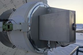
This photo was taken using my iPhone 6 on Nov-21, 2017 at 2:06 PM while Johnson and Tashun were loading the receiver into the receiver cabin with Kim (Vectrus contractor) operating the TEREX. It was my first trip to Thule Air Base, Greenland, where the temperatures were hovering around -25 C. We achieved astronomical first light the following month in December and is an attestation to the tremendous dedication and effort put forth by the technical and science staff.
The antenna has a diameter of 12 meters and was designed to observe at frequencies of up to 950 GHz with a potential surface accuracy of 16 um RMS (~lambda/20), though we are not there yet. The receiver cabin is visible just below the primary reflector and moves in elevation with the dish. The rectangular structures are referred to as "left side container" and "right side container" as viewed from this perspective and house ancillary equipment.
My involvement with the GLT
I joined the GLT project in 2012 at ~20% level of effort to support the hardware system design with my Taipei colleague Johnson Han. My commitment increased to ~80% in June of 2016 to complete the detailed designs for the LO and fiber systems.
Engineering activities
Integration of Redesigned Holography Reference Receiver Unit

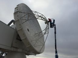
2019-Oct - My 4th trip to Thule Air Base to test the redesigned holography system with Satoki and Nimesh. Here Satoki and I are rotating the Reference Receiver on the secondary by 90 degrees on a windy day with temperatures hovering below -20 C (D. Kubo, S. Matsushita, photo courtesy of N. Patel).
This video shows Satoki driving the telescope from maintenance stow (elevation 90 deg) to the holography beacon position (elevation 2.7 deg), it's impressively quiet and smooth:
https://www.dropbox.com/s/nu0cjdxe1t06nn9/9343A5D6-52BF-4B43-86A5-B86B8AD75F29.mov?dl=0
Reference Receiver Unit Mounted on Secondary
2019-Oct - Configuration of Reference Receiver after rotation to vertical (E-field) polarization to match what we did with the transmitter on South Mountain to reduce potential ground reflections (D. Kubo, S. Matsushita).
Transmitter on South Mountain after rotation to vertical polarization (I bought those C-clamps at the Base Exchange):
https://www.dropbox.com/s/fzbah5mruwa4knd/rotatedbeacon.jpeg?dl=0
First Detection of the 94.5 GHz Beacon with Redesigned Reference Receiver Unit
First Detection of the 94.5 GHz Beacon with Redesigned Reference Receiver Unit
2019-Oct - This photo is of the first detection of the 94.5 GHz beacon on South Mountain with the redesigned receiver. Long story short, it turned out that the 6th harmonic of the 15.75 GHz pilot tone generated within the Photonics Transmitter unit interfered with the beacon reception (D. Kubo, S. Matsushita).
Holography Reference Receiver Unit Tests in Hilo
Integration of Final LO Photonics Transmitter Unit
First Detection of the 94.5 GHz Beacon with Redesigned Reference Receiver Unit
2019-Aug - Photo of Ryan testing the receiver along with the new Down Converter plate with the spare GLT science receiver at the JCMT facility across the street. A 94.5 GHz test beacon was used to stimulate both receivers (D. Kubo, R. Chilson, C.C. Han).
Lab test results:
https://www.dropbox.com/s/jorkw04c9spfieg/20190829_Holo_RefRx_LOG.pdf?dl=0
Redesign of Holography Reference Receiver Unit
Integration of Final LO Photonics Transmitter Unit
Integration of Final LO Photonics Transmitter Unit
2019-Jul - This Reference Receiver was redesigned in Hilo to utilize the same LO references as the science receiver. This is a photo of Ryan completing the final assembly along with the new Down Converter plate in our Hilo receiver lab (D. Kubo, R. Chilson).
Updated holography system design:
https://www.dropbox.com/s/ao2rss7n0ioewhl/HoloSystemRedesign2019-08-08A.pdf?dl=0
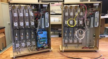
Integration of Final LO Photonics Transmitter Unit
Integration of Final LO Photonics Transmitter Unit
Integration of Final LO Photonics Transmitter Unit
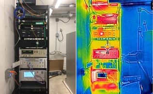
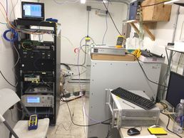
2019-Jun - My 3rd trip to Thule Air Base for integration and test of the final LO Photonics Transmitter unit. Left photo - rearranged rack with Transmitter located just above the E8257D synthesizer (blue display), right - thermal image of rack captured with our new FLIR EX-6T camera (D. Kubo).
15.75 GHz pilot tone round-trip phase stability performance:
https://www.dropbox.com/s/h2090y1srwzbb4d/2019-11-8A-maserhouse_and_fiber.pptx?dl=0
I gave this SMA Lunch Talk over Zoom in Aug-2020 to describe the GLT fiber, LO, and IF subsystems:
https://www.dropbox.com/s/ae8sq7wszkhdhy9/Kubo_LunchTalk_20200804c.pptx?dl=0
Back-to-Back Testing of LO Subsystem
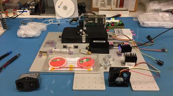
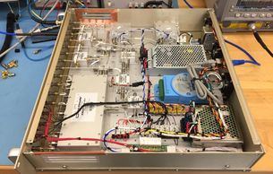
LO Photonics Transmitter Unit (bottom view)
LO Photonics Transmitter Unit (top view)
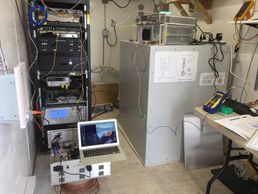
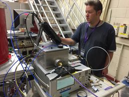
2019-Jun - The LO Photonics Receiver was removed from the antenna receiver cabin to perform back-to-back testing with the Photonics Transmitter. I'm using my MacBook Air in this photo to adjust the EDFA gain in the Transmitter. The large box on the right is the T4S iMaser 3000 hydrogen maser, courtesy of Gordon & Betty Moore Foundation. Sitting on top is a Keysight N9010A spectrum analyzer and the Photonics Receiver.
Description of LO phase noise test setup and performance:
https://www.dropbox.com/s/7fxpz8116dh33ls/LO_PhotonicsPhaseNoisePerformance.pdf?dl=0
LO Photonics Transmitter Unit (top view)
LO Photonics Transmitter Unit (bottom view)
LO Photonics Transmitter Unit (top view)
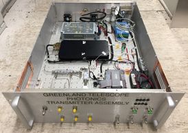
2019-Jun - Top view photo of LO Photonics Transmitter unit with cover removed for physical inspection. The unit provides optical transmission of 3 signals consisting of 100 MHz maser reference, 15.75 GHz pilot tone, and 18 to 31.5 GHz LO over a wavelength of 1557.2 nm from the maser house to the telescope receiver cabin over a signal fiber and works in conjunction with the Photonics Receiver unit. The 100 MHz and LO consist of ultra low phase noise references to satisfy VLBI requirements. The 15.75 GHz pilot tone is received in the receiver cabin and retransmitted back to this unit over the same fiber at 1561.1 nm for round trip amplitude and phase measurement (D. Kubo, R. Chilson).
Description of the unit on the ASIAA website:
https://www.asiaa.sinica.edu.tw/gallery/show.php?i=48711039449b9de38c76d1438c8846f0
LO Photonics Transmitter Unit (bottom view)
LO Photonics Transmitter Unit (bottom view)
Initial Holography System Integration in Thule
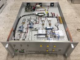
2019-Jun - Bottom view photo of LO Photonics Transmitter unit with cover removed for physical inspection just after arrival in Thule Air Base. I transported this unit as check-in luggage from Hilo and it survived the journey without incident. This unit was designed, manufactured, and tested in our Hilo office. A big thanks to Ryan for his craftsmanship assembly work (D. Kubo, R. Chilson).
A slightly dated (2018-Feb) LO subsystem description:
https://www.dropbox.com/s/b6syg462xvz9rmd/LO%20Subsystem.pptx?dl=0
Schematic of this unit:
https://www.dropbox.com/s/26aejezhh11isvg/2020-03-11%20Photonic_Tx.pdf?dl=0
Initial Holography System Integration in Thule
Installation of Holography Reference Receiver Unit onto the Telescope
Initial Holography System Integration in Thule
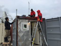
2018-Sep 6 - My 2nd trip to Thule Air Base was rerouted to Kangerlussauq for an overnight stay due to poor weather. I arrived in Thule the next morning on Friday to work on the integration and test of the holography system.
Condensed summary - Resultant phase noise between reference and science receivers was too large to produce useful maps and was determined to be caused by independent LO generation schemes:
https://www.dropbox.com/s/1z4132h6sp7azeg/F2F%202019-05-10%20Holo.pptx?dl=0
Installation of Holography Reference Receiver Unit onto the Telescope
Installation of Holography Reference Receiver Unit onto the Telescope
Installation of Holography Reference Receiver Unit onto the Telescope
2018-Sep - Tashun installing the receiver onto the telescope for a second time after troubleshooting on the ground (T.S. Wei, D. Kubo).
The holography system was originally designed by SAO (T.K. Sridharan, P.S. Leiker) with two nearly identical receivers, one on the secondary and the other in the receiver cabin with both utilizing the same set of reference LOs. However, mechanical interference with the 3-cartridge dewar prevented mounting of the main receiver in the cabin so we used the 90 GHz science receiver in it's place.
Holography system diagram:
https://www.dropbox.com/s/hvtc51hxkyefkv5/Holo%20System%20Block%202018-09-26a.pdf?dl=0
Testing the Holo. Reference Receiver Unit on the Maser House Roof
Installation of Holography Reference Receiver Unit onto the Telescope
Installation of Holography Reference Receiver Unit onto the Telescope
2018-Sep - Our initial tests with the reference receiver on the telescope yielded a very weak detection (~40 dB low) of the 94.5 GHz beacon on South Mountain, ~3 km distance. We removed the reference receiver from the telescope and retested on the roof of the maser house and confirmed the problem.
Weak detection spectra:
https://www.dropbox.com/s/gxvx3y27hdblgsl/beaconspectra.jpg?dl=0
Trouble-shooting Low Gain of Holo. Reference Receiver Unit
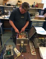
2018-Sep - I disassembled the reference receiver and spent about two days investigating the reason for the weak detection. Fortunately I brought a harmonic mixer and waveguide horn so that I could generate a 94.5 GHz test tone to simulate the beacon while troubleshooting. The problem turned out to be an intermittent DC power connection in a Molex connector and was quickly repaired by Joshua (D. Kubo, S.H. Chang).
Simulating 94.5 GHz, -84 dBm beacon tone for testing:
Holography Backend Hardware
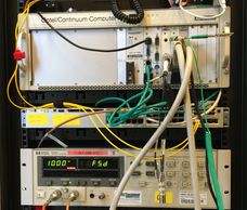
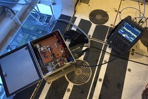
2018-Sep - The 94.5 GHz beacon signal is received separately in both the reference (A) and science (B) receivers, dual down converted to 21.4 MHz, and sent to the HP 8508A vector voltmeter (bottom of photo) in the Left Side Container. The rear panel analog outputs representing B-A phase and B-amplitude are digitized by a compact PCI module in the Advantech PC (D. Kubo, C.W.. Huang).
Holo. Science Receiver Down Converter & LO Source Plate
Holo. Science Receiver Down Converter & LO Source Plate
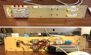
2018-Aug - Just prior to my departure to Thule Air Base, I assembled this Down Converter and Reference LO plate in Hilo using spare parts and pieces in the lab. It mixes the 8.1714 GHz beacon tone from the science receiver with 8.150 GHz LO to produce 21.4 MHz which is sent to the vector voltmeter. The Valon 5009 on the front panel is a programmable frequency synthesizer phase locked to 10 MHz and produces 100 MHz and 1.5214 GHz LOs for the reference receiver. This down converter plate has since been replaced by a new one developed in 2019 (D. Kubo).
Integration and Test of LO Subsystem
LO Photonics Receiver Unit (bottom view)
Holo. Science Receiver Down Converter & LO Source Plate
2017-Nov-16 - My 1st trip to Thule Air Base to work on the integration & test of the LO subsystem and completion of the fiber optic system that Peter worked on prior to my arrival. It was a very busy time in the project with everyone working full out to achieve our first light goal before the end of the year (D. Kubo, P. Oshiro).
First light on Christmas Day 2017 (S. Matsushita, J.Y. Koay:
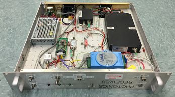
LO Photonics Receiver Unit (top view)
LO Photonics Receiver Unit (bottom view)
LO Photonics Receiver Unit (bottom view)
2017-Nov-2 - This Photonics Receiver unit was designed, assembled and tested chiefly by a single individual (said unabashedly of myself) and operates in conjunction with a suite of other units within the LO subsystem. With the exception of the round-trip phase monitoring portion, the entire LO subsystem was integrated and tested at Thule AB in November of 2017 (D. Kubo, EAO machining).
Description of the unit on the ASIAA website:
http://www.asiaa.sinica.edu.tw/gallery/show.php?i=9bc513515828624144d267ed0cbee5e8
LO Photonics Receiver Unit (bottom view)
LO Photonics Receiver Unit (bottom view)
LO Photonics Receiver Unit (bottom view)
2017-Nov-2 - Testing was completed about a week prior to my departure to Thule Air Base and I had packed this and the temporary Photonics Transmitter into a Pelican case and brought it with me as check-in luggage. The weeks leading up to this point were extremely hectic as I was also leading the fiber optic system design activity.
Schematic of this unit:
https://www.dropbox.com/s/ov2hrpotcm4oj3z/2019-09-11%20Photonic_Rx.pdf?dl=0
Final Testing of LO Photonics Receiver Unit in Hilo
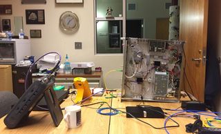
2017-Nov-3 - Final testing of monitor and control function of the Photonics Receiver in my office while multitasking on the fiber optic system (D. Kubo).
RF Testing of LO Subsystem in Hilo
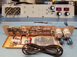
2017-Oct-12 - Final RF testing of the LO Photonics system in Hilo. Left to right, Keysight N9010A spectrum analyzer, LO Photonics Receiver, temporary Photonics Transmitter. The 100 MHz and 18 to 31.5 GHz synthesizer are on the floor below the bench (D. Kubo).
Preliminary test data package:
https://www.dropbox.com/s/6axsnbztix6e5xz/LO_Transmission_Prelim_2017-09-14a.pdf?dl=0
Assembly of LO Photonics Receiver Unit
Installation of Fiber Optic I/O Chassis, Receiver Cabin
2017-Aug-25 - Early assembly phase of LO Photonics Transmitter unit where I'm contemplating the mechanical layout. I had designed this universal aluminum deck plate for the ALMA project a few years earlier and decided to use it again (D. Kubo, deck plate fabricated in Taipei courtesy of C.C. Han).
Installation of Fiber Optic I/O Chassis, Receiver Cabin
Installation of Fiber Optic I/O Chassis, Receiver Cabin
2017-Nov - Photo of a partially complete fiber optic chassis installation in the receiver cabin left rack. I installed a total of 7 chassis during this trip: 2 in antenna receiver cabin; 1 each in the antenna left and right side containers; maser house; control trailer; and VLBI trailer. Peter had completed the fusion splices about two weeks prior to my arrival (D. Kubo).
Fiber optic system deployment:
https://www.dropbox.com/s/mah33ii2dywfic3/Fiber%20Optic%20System.pptx?dl=0
Installation of Fiber Optic I/O Chassis, Right Side Container
2017-Nov - Photo of completed fiber optic chassis (cover removed) in the antenna right side container. There are a total of 12 fiber cables, each containing 4 Verrillon VHS100 low temperature single-mode fibers rated to operate down to -65 C. I selected SC/APC as the default optical connector and each 1U chassis can support 12 connections. A 2U chassis is used in the control container and can support up to 24 SC/APC connections.
Custom low temperature fiber optic cable:
https://www.dropbox.com/s/tnzxm1tcobq4172/DNS-12215.pdf?dl=0
Fiber Optic System Design
2017-Aug - Due to a shortage in our technical staff I ended up designing and ordering the hardware for the fiber system in parallel with working on the LO subsystem. After ordering the fusion equipment, I borrowed Peter from YTLA and flew to San Jose for a 1-day training session a week prior to traveling to Thule AB in September for splicing. Major kudos to Jackie in Taipei for pulling off the large procurements and to Peter for fusion splicing. I went to Thule in November to install & test the LO subsystem and to complete fiber installations and tests with the terminal equipment. First light for the telescope was obtained a month later in December 2017. (D. Kubo, P. Oshiro, J. Wang, S.H. Chang, ICP)
Early fiber interconnect diagram:
https://www.dropbox.com/s/29gqp3d5ekk9km2/GLT_Fiber_Cables_2017sep8.pdf?dl=0
Crash Course on Fusion Splicing with Fujikura Equipment
Crash Course on Fusion Splicing with Fujikura Equipment
Crash Course on Fusion Splicing with Fujikura Equipment
2017-Aug-30 - Peter and I had a one day crash course training session in San Jose, CA. Peter traveled to Thule Air Base the following week and performed all of the required fusion splices. We put this training to practice in very short order (D. Kubo, P. Oshiro).
Fiber optic system status memo:
https://www.dropbox.com/s/7io0eg2d5xxtomd/Memo_DK006_2017_Fiber_Status.pdf?dl=0
Packaging the Splice Trays into the Cabinets
Crash Course on Fusion Splicing with Fujikura Equipment
Crash Course on Fusion Splicing with Fujikura Equipment
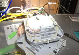
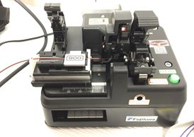
2017-Nov - As it turned out, I broke a few fibers while manipulating the splice trays into the splice cabinets which arrived in Thule too late for Peter to install. You can see the yellow glass fibers (125 um diameter) protruding from the black cable. The following series of photos were of my first attempt at fusion splicing with our new Fujikura equipment.
Stripping Polyimide Coating from Fiber
Crash Course on Fusion Splicing with Fujikura Equipment
Stripping Polyimide Coating from Fiber
2017-Nov - One of the drawbacks of using the VHS100 low temperature fiber is that it requires this Fujikura PCS-100 polyimide coating stripper. Normal acrylate coatings can be removed with a handheld mechanical tool or thermal stripper.
Cleaving Fiber
Post Fusion Splice
Stripping Polyimide Coating from Fiber
2017-Nov - After stripping the VHS100 fiber, the pigtail fiber (brown in photo) with normal acrylate coating is stripped using a thermal stripper. Thereafter, each fiber is cleaved using this CT-101 to produce clean 90 degree ends.
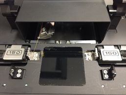
Pre Fusion Splice
Post Fusion Splice
Post Fusion Splice
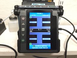
2017-Nov - After cleaving the fibers are installed into the 70S fusion splicer and cleaned with an arc flash prior to fusion.
Post Fusion Splice
Post Fusion Splice
Post Fusion Splice
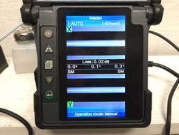
2017-Nov - Post fusion view of the fused fiber. The tricky part is removing the fiber from the machine and sliding a protective sleeve over the fusion and into the heater for shrinking without breaking the fiber.
BDC Extension Plate
Backend LO Reference Unit
Backend LO Reference Unit
2019-Jan - This BDC extension plate (x2) was designed to facilitate the use of the EHT BDCs in place of our IF Processor units. Each of the two plates provide switch selection of a pair of IFs from the 3 receivers (86, 230, or 345 GHz) as well as AGC signal conditioning and routing to auxiliary instruments which the EHT BDC unit does not provide. Kudo's to Ryan for his timely and craftsmanship design and assembly work (R. Chilson, D. Kubo).
Link to EHT BDC extension plate installation memo:
https://www.dropbox.com/s/ee2ndmb7d0nbclx/Memo_DK001_2019EHTBDC_Install.pdf?dl=0
Backend LO Reference Unit
Backend LO Reference Unit
Backend LO Reference Unit
2017-Sep - As part of the LO subsystem, I defined the unit requirements and procured the long lead PLOs for the 2nd LOs (3.85, 8.15 GHz) and clock (2.048 GHz). Ryan performed the detailed work of design, parts procurement, fabrication, assembly and test. This unit + 1 spare has been deployed to Thule AB as of November 2017. Kudos again to Ryan for the beautiful work (R. Chilson, D. Kubo).
A slightly dated (2018-Feb) LO subsystem description:
https://www.dropbox.com/s/b6syg462xvz9rmd/LO%20Subsystem.pptx?dl=0
IF Processor Unit
Backend LO Reference Unit
Electronics System Design
2017-Apr - Design for this IF Processor unit was developed around our earlier SMA BDC work in 2014 prior to our knowledge of the EHT BDC which was being conducted in parallel. This unit has since been replaced by the EHT BDC for project conformity with the other EHT sites. Again, kudo's to Ryan for his timely and craftsmanship design and assembly work (R. Chilson, D. Kubo).
Description of the unit on the ASIAA website:
https://www.asiaa.sinica.edu.tw/gallery/show.php?i=b2ce4538870f4aac20c0cb731e5e4862
Electronics System Design
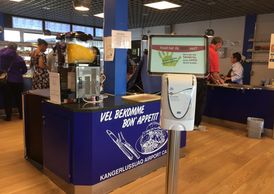
Thule Dundas Buffett Restaurant
Electronics System Design

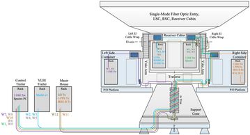
2012-Jun - My initial involvement with the GLT project was in June of 2012 where I was tasked with developing the electronic system architecture. I was familiar with the ALMA system diagrams and decided to follow suit starting with our existing receiver and backend digital hardware technologies. And later after careful consideration, I developed the Local Oscillator (LO) and Intermediate Frequency (IF) portions in between. A large fraction of this effort involved the design of a system amenable to remote operations and monitoring of phase and amplitude signal stabilities associated to mm-wave VLBI requirements. This diagram has evolved to include several other systems/subsystems including fiber optics, network and computing, calibration, holography and others.
A Taipei colleague and I continue to maintain this drawing to reflect the “As Built Configuration” in Thule AB. We are currently on Rev-0U, 21st revision (D. Kubo, C.C. Han, M. Inoue, S. Matsushita, K. Asada):
https://www.dropbox.com/s/2fxpxqaaegomg2i/Electronics_System_Block_2022-8-3_0U.pdf?dl=0
2018 SPIE conference article:
https://arxiv.org/abs/1806.07525
Thule Dundas Buffett Restaurant
Thule Dundas Buffett Restaurant
Thule Dundas Buffett Restaurant
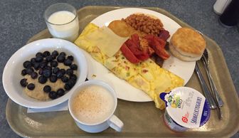
I'm not such a picky eater so eating at Dundas is fine for me, at least for the 2 week period that I'm normally there. Others who stay longer generally cook their own meals in the dorm or hotel common areas. There's a Base Exchange that sells groceries and other goods.
If you are interested in going to Thule here's some information for military personnel, some of which is applicable to civilians like myself:
https://download.militaryonesource.mil/12038/Plan%20My%20Move/Thule%20Information.pdf
Thule Fitness and Sport Center
Thule Dundas Buffett Restaurant
Thule Dundas Buffett Restaurant
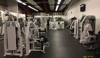
The gym at Thule Air Base is probably one of the nicest one's I've been to. Very large facility with both cardio and weight training equipment. And best of all not crowded. There are a lot of classes offered each week such as spin, yoga, fitness, etc, though I haven't tried any of them yet.